Training
Features
Multifunction display capability, featuring ECDIS, Conning Information Display, Radar/Chart Radar* and Alert Management System**

ECDIS
Conning Information Display
Radar


* Radar sensor needs to be integrated in the network.
** Radar and Alert Management System display capabilities are to be implemented as software upgrade. (option)
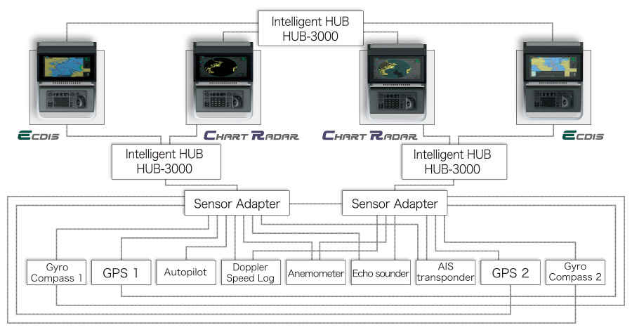
Sample system configuration
-
Sensor adapter facilitates installation and maintenance
The sensor adapters act as central medium to gather all the sensor data and collectively feed it to ECDIS and Chart Radar in the system. Since the sensor adapters can be extended to cover all the sensors within the system, individual cablings in the sensor-to-ECDIS/Radar interface can be greatly reduced.
Navigation sensors can be directly interfaced with the ECDIS processor’s 8 serial I/O ports.
Sensor adapters are required under the following conditions
Sensor adapter(MC-3000S/3010A/3020D/3030D)- The sensor data is to be shared amongst multiple networked ECDIS and Radar systems.
- The number of sensors interfaced is more than the number of the ports the processor has (8 serial I/O ports, 1 digital IN and 6 digital OUT), and/or
- The networked sensors include analog sensors.
In order to integrate onboard sensors into the navigation network, the sensor adapter may be interfaced with the inteligent hub HUB-3000 from which distribution of the sensor data throughout the network is possible.
Alternatively, multiple sensor adapters may be interfaced via Ethernet to integrate onboard sensors for use in the shipboard network.
Instantaneous chart redraw delivered by FURUNO’s advanced chart drawing engine, making redraw latency a thing of the past

Based on nautical chart information and superimposed navigational information on the screen, it is possible to determine planned routes accurately and quickly
Detailed changes can be made easily, and navigation monitoring by displaying data from various sensors is supported.
Interface with FAR-2xx8 series Radar and FAR-2xx7 series Radar for Radar overlay, target track info, route and waypoint exchange via Ethernet
*Software update on FAR-21x7/FAR-28x7 series might be necessary depending on the program number.
Complies with the following IMO and IEC regulations
- IMO A.694(17)
- IMO MSC.191(79)
- IMO MSC.232(82)
- IMO MSC.302(87)
- IEC 60945 Ed. 4
- IEC 61162-1 Ed. 5
- IEC 61162-2 Ed. 1
- IEC 61162-450 Ed. 2
- IEC 61174 Ed. 4
- IEC 62288 Ed. 3
27" wide LCD monitor (Model: MU-270W) selectable

- Easy switching of the screen between DVI1 and DVI2 with a locally supplied switching box
- Automatic switching the signal source from DVI1 to DVI2, when the DVI1 signal fails
Compatible Cartography
-
IHO/S-57 Edition 3 vector chart (IHO S-63 data protection scheme)
- Admiralty Vector Chart Service (UKHO)
- C-MAP CAES
- Jeppesen Primar ECDIS Service
- ARCS raster chart
-
C-MAP Professional+*
*C-MAP Professional+ is a private chart, hence not construed as replacement for paper chart. - Compatibility with Admiralty Information Overlay (AIO)
Additional AIO layer includes all Admiralty Temporary and Preliminary Notices to Mariners as well as additional ENC Preliminary Notices to Mariners, i.e., reported navigational hazards that have been incorporated into paper chart but have yet to be included in ENCs. The service is free of charge as part of Admiralty Vector Chart Service (AVCS) by UKHO.

Electronic Navigational Chart (ENC)
Raster Navigational Chart (RNC)


AIO data layer displayed
Place the cursor on the AIO object and right-click to open the contextual menu. Select “Object INFO” to open the chart object window.

Chart object window
On the chart object window, select the AIO object and click "OK" to view the details.
(bottom left image)The full text of the Notice to Mariners as well as associated diagrams can be displayed subsequently.
User Interface
Use of a new user interface system enables PC manipulation
ECDIS Control Units
The operator control of the FMD-3005 can be done with the ECDIS Control Unit RCU-024 or the Trackball Control Unit RCU-026. All functions of the ECDIS can be accessed by using the trackball, scrollwheel and left/right clicking.
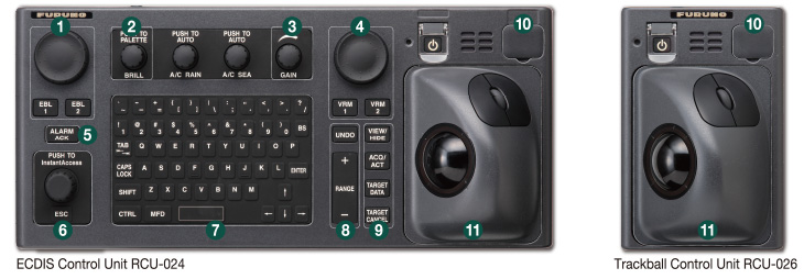
 Press “EBL 1” and “EBL 2” to activate/deactivate respective EBL; and rotate the encoder to adjust active EBL.
 Rotate to adjust brilliance level of the FURUNO monitor; and press to select display palette.
 Rotate to adjust radar gain on the radar overlay.
 Press “VRM 1” and “VRM 2” to activate/deactivate respective VRM; and rotate the rotary encoder to adjust active VRM.
 For acknowledgement of alerts generated.
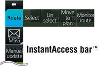
 Rotate to select items within the InstantAccess bar™; and press to confirm the selection of the item.
 Full QWERTY keyboard for easy entery of route, event and waypoint names.
 Following functions are assigned for each key:
UNDO to undo the last operation RANGE to select chart scale -
 Following functions are assigned for each key:
VIEW/HIDE to show/hide the I.A. bar and route information window ACQ/ACT to activate selected active AIS target TARGET DATA to display the detailed target data for selected TT/AIS TARGET CANCEL to sleep the selected active AIS target  USB port for charts update, import/export, WP/routes, user setting.
-
 Trackball Module
Trackball module consists of four parts, each of which has the following functions:
trackball to move the cursor and select an object left-click to perform/confirm the action related the selected object right-click to display contextual menu while a cursor is on the display area, and to cancel action done on the selected object scrollwheel to select menu items
|
|
 Contextual Menu
Task-based user interface realized by combination of Status bar and InstantAccess bar™ providing quick access to the needed tasks/functions
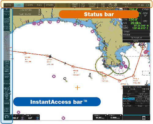
The user interface of the FMD-3005 centers on carefully organized operational tools: Status bar and InstantAccess bar™.
The Status bar at the top of the screen contains information about the operating status, i.e., MFD operating mode, the ECDIS operation modes, etc. InstantAccess bar™ at the left-hand side of the screen contains all the tasks (functions/actions) corresponding to the ECDIS operation mode currently selected. These operational tools deliver straightforward, task-based operation by which the operator can quickly perform navigational task without having to go deeper into an intricate menu tree.
Software Version
| Software version | 5.xx* |
|---|---|
| Testing standard | IEC 61174 Ed.4 |
| Electronic Navigational Chart (ENC) | S-57 Ed. 3.1, S-57 Ed. 3.1.1, S-57 Maintenance Document (Cumulative) No. 8 |
| Raster Navigational Chart (RNC) | S-61 Ed. 1.0 |
| ECDIS Presentation Library | S-52 PresLib Ed. 4.0 |
| Chart Content and Display Aspects of ECDIS | S-52 Ed. 6.1 |
| ENC Data Protection | S-63 Ed. 1.2.0 |
| Compliance for IHO CDS | S-64 Ed. 3.0.1 |
| Bridge Alert Management (BAM) | IEC 62923-1/2 |
* This software version is required only for the installation onboard vessels applicable to MED Implementing Regulation (EU) 2020/1170. Please consult with your local distributors, should you wish to upgrade the software.
Brochure Download
Contact
